Fitting Smith tacho, positve earth

Post any technical questions or queries here.
Post Reply
User avatar
Tedwong
998 Cooper
Posts: 468
Joined: Thu Jun 24, 2010 4:48 pm
Location: Hong Kong
Been thanked: 2 times

Fitting Smith tacho, positve earth

Post by Tedwong »

Hi, can I ask for advice of fitting of a Smith tacho, to my MK1 which is positive earth.
The other early Smith tacho(also with square letters, but negative earth) has 3 connectors at the back. But this one only has one. Where should that connect to? Also, for the pulse sensing loop, is it matter for the direction of connection, ie. which way to coil and which way to fuse(please correct me if I'm wrong)

Thank you very much!
Ted

Image
Image
mini129
850 Super
Posts: 111
Joined: Thu Jun 24, 2010 10:21 pm

Re: Fitting Smith tacho, positve earth

Post by mini129 »

Ted, the wiring diagram is in the main section of the mk1 site
http://mk1-performance-conversions.co.u ... acho_2.jpg
User avatar
Tedwong
998 Cooper
Posts: 468
Joined: Thu Jun 24, 2010 4:48 pm
Location: Hong Kong
Been thanked: 2 times

Re: Fitting Smith tacho, positve earth

Post by Tedwong »

Hi, thank you for the headup!
Yes, quite clear now.
But few more questions, as compare to the original wiring diagram, the tacho should have 3 connectors, mine only has one.
Can I assume its connect to the Fuse?
Also, seems the direction of the pulse loop is important, if my loop has not got the red/black markers as mentioned in the instruction, how can I determine?

Thanks again!
Ted
mini129
850 Super
Posts: 111
Joined: Thu Jun 24, 2010 10:21 pm

Re: Fitting Smith tacho, positve earth

Post by mini129 »

When i think about it only the early pulse loop Smiths tacho's were designed for neg and pos earth connection as the circuit was isolated ie: the ones with three threaded terminals on one side of the case. Your single blade terminal is the positive terminal for a negative earth configuration. The negative 'terminal' connected to the negative side of the battery is the case of the tacho in this instance. Make sense :? It can be converted to positive earth if necessary although most of the ones I do are for the reverse as very few people change a car from neg to pos earth! Luckily I have a nice 1962 850 Mini positive earth test rig :lol: I needed it recently when I replaced the circuit in a speedwell weston tacho for a car that is positive earth.
The pulse loop direction is important but not critical from the point of view of connecting it round the wrong way whilst testing and blowing it up! so once the polarity is sorted out try connecting both ways.
User avatar
Tedwong
998 Cooper
Posts: 468
Joined: Thu Jun 24, 2010 4:48 pm
Location: Hong Kong
Been thanked: 2 times

Re: Fitting Smith tacho, positve earth

Post by Tedwong »

Hi Mini129, thanks for the investigation!
I'm now thinking that this tacho, as you suggested is actually a negative earth one and converted to positive earth???
In this case, where the single connector I should connect to? For my Positive earth Mini?
The casing of the tacho when fitted is obviously connected to the earth of the car, which in fact is the positive of the battery?
Sorry if I'm looks like confused! :oops:

Ted
RS6
850 Super
Posts: 132
Joined: Thu Jun 24, 2010 12:35 pm
Been thanked: 1 time

Re: Fitting Smith tacho, positve earth

Post by RS6 »

.
Last edited by RS6 on Tue Mar 05, 2013 6:43 pm, edited 1 time in total.
mk1
Site Admin
Posts: 19846
Joined: Thu Jun 24, 2010 11:30 am
Location: Away with the Faries
Has thanked: 3 times
Been thanked: 8 times

Re: Fitting Smith tacho, positve earth

Post by mk1 »

Ted,

IF your tacho has definitely been converted to positive earth, then the terminal on the back MUST be negative. With the positive being the case & the pulse wire being the pulse wire.

Good luck.

M
62Countryman
850 Super
Posts: 129
Joined: Mon Jun 28, 2010 1:14 pm
Location: US

Re: Fitting Smith tacho, positve earth

Post by 62Countryman »

Ted,

I looked at the wiring diagram (impulse) and it looks like the tach should work, You make a loop via the plastic connector and feed one side of the loop to the ignition (place to get power). The other side of the loop goes to the ignition coil. The other terminal (spade) should go to ground. I am almost 100 percent this is the correct wiring without seeing a Smiths Installation Pamphlet.

Good luck.
mk1
Site Admin
Posts: 19846
Joined: Thu Jun 24, 2010 11:30 am
Location: Away with the Faries
Has thanked: 3 times
Been thanked: 8 times

Re: Fitting Smith tacho, positve earth

Post by mk1 »

The induction wire on an impulse tach goes between the coil & the points replacing the CB wire. This cannot give an actual electrical supply to the tacho.

All impulse tachos need a live feed, a negative feed & the impulse loop. The tacho works by measuring the current induced by the trigger wire as it goes through a magnetic field created by a coil fed by the live & neutral terminals.
mini129
850 Super
Posts: 111
Joined: Thu Jun 24, 2010 10:21 pm

Re: Fitting Smith tacho, positve earth

Post by mini129 »

62 Countryman is correct for wiring in an original equipment installation in an mgb, escort etc. Mark is correct for aftermarket installations. Both will work. The fact that the case has been freshly plated suggests that the tacho has been apart.If you really get stuck post it to me and I will test it Ted.
User avatar
Tedwong
998 Cooper
Posts: 468
Joined: Thu Jun 24, 2010 4:48 pm
Location: Hong Kong
Been thanked: 2 times

Re: Fitting Smith tacho, positve earth

Post by Tedwong »

Hi all, thank you so much for the imput, and mini129 thanks for the offer, really appreciated! Hope I can get it run, or I'll definitely seek your help!

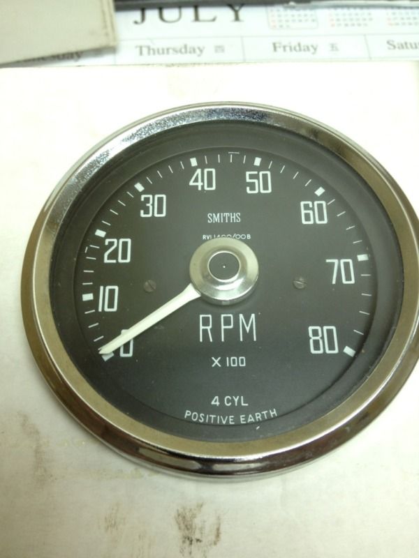
Ok, back the tacho, looking at it again I too guess it was a later gauge that got convert inside and on the face.
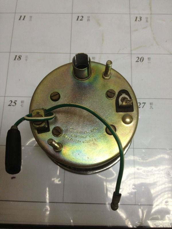
So, as Mark said, the single blade must be negative but still connect to the fuse(live feed???), although it is infact to the negative of the battery, as other equipments on this Positive earth car did??? Am I wrong?

But, one interesting thing as by mini129, when looking at the 2 different fitting instructions from Mark's site, the 1st one said the loop is connect to coil AND fuse block(as pointed out by 62countryman). But for the 2nd instruction, the loop is connect to coil AND dizzy(as point out by Mark). Killing me!!! :roll:
User avatar
Tedwong
998 Cooper
Posts: 468
Joined: Thu Jun 24, 2010 4:48 pm
Location: Hong Kong
Been thanked: 2 times

Re: Fitting Smith tacho, positve earth

Post by Tedwong »

Hi all, some updates on my installation. The good is it works!!!
I connected the impulse loop one end to coil and another to dizzy(just a guess on the direction), the single connector to the fuse to get live(earth), finally the casing to the body. Bingo! It move in the right direction. The very 1st time I know my 850 moving at 1000rpm!
Thank you so much for the information so far!
The only thing this tacho seems dose not provide a "hole cover with rubber grommet" for calibration, as found on other older Impulse Tachos. Any idea mini129???

Cheers
Ted
mk1
Site Admin
Posts: 19846
Joined: Thu Jun 24, 2010 11:30 am
Location: Away with the Faries
Has thanked: 3 times
Been thanked: 8 times

Re: Fitting Smith tacho, positve earth

Post by mk1 »

Glad you got it working Ok.

M
Post Reply