8 ports cylinder Head project
Posted: Wed Aug 02, 2023 11:45 pm
Hi everyone,
I don't know if this is the right place to talk about this project, but feel free to move it if you need to.
For those of you who don't know me, let me introduce myself quickly. I've been working on minis since I was twelve thirteen years old, and I've learnt a lot with these cars (carburetion, ignition, mechanical design, etc.).
Now, as an industrial engineering student, I wanted a project that was a bit more substantial and complete than what I'd been able to do up until now.
As some of you know, I have been working for a while time on the modelling of 8 port cylinder heads.
(as Trog was able to do with his cylinder head, thanks for sharing!)
The obejctive would be to revive the group two cylinder head.
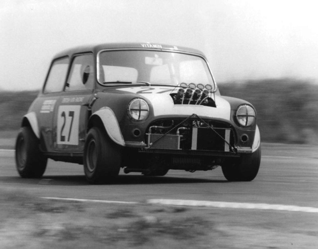
So the first step was to read the documentation for this competition.
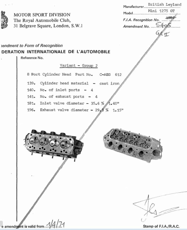
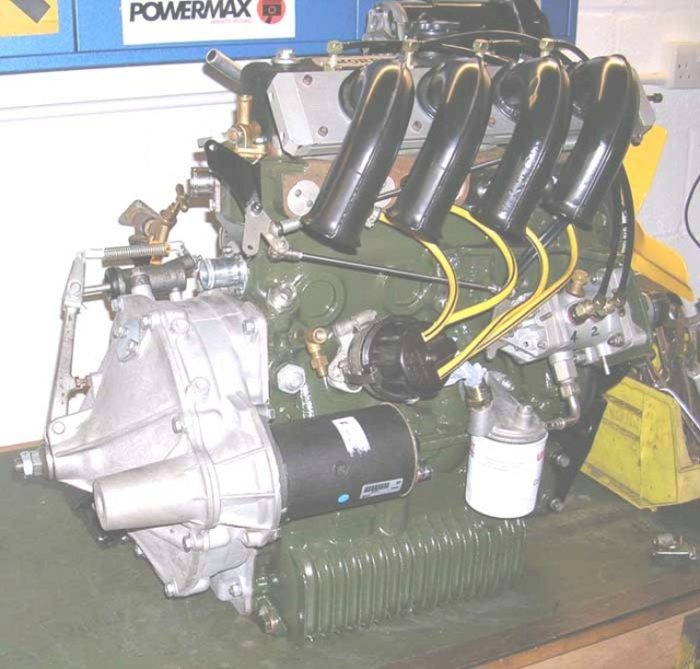
(source mk1 forum)
and finally, the regulations only require a few elements to be able to respond to this group's cylinder heads, which is good news!
After a year's research, I was able to start the work of modelling, understanding and analysing, which will enable this model to be competitive.
This work required a lot of time, a number of simulations, and also the development of a number of 3D printed prototypes.
The first of many steps was to determine the location of the important components of the cylinder head, i.e. the studs, the rocker arm passages, the coolant passages and the oil passages.

Once the elements had been designed, I printed them out to check the accuracy of the design.
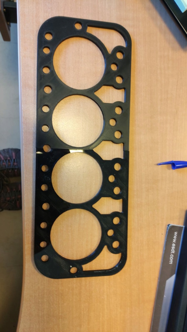

Next step, the shape of the intake and exhaust ducts and the combustion chamber had to be determined.
Although as an engineering student I have access to interesting resources, but this part was extremely time-consuming.
The following images are not from the latest simalutions or designs (to protect my work I hope you'll understand). .
But they are useful for illustrating the post.
As you can see, I carried out a number of CFD simulations in order to optimise the flow of the cylinder head.
This was useful, because it's 'quite complicated' to predict how a fluid will react depending on its velocity and the shape of the duct through which it flows.
The influence of the shape of the intake manifold on the flow is important, and simulations make it easier to interpret the results.

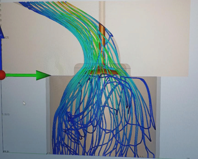

(non-contractual photo)
finally, after a few (many) hours, I managed to get a complete design
I've printed the whole thing out to check it.
but as it's a big piece, i had to do it in four parts, you can see the joins and the lack of detail, effectively it's a lightened version because concerning the time it's the equivalent of more than 4 days of printing 24/24.

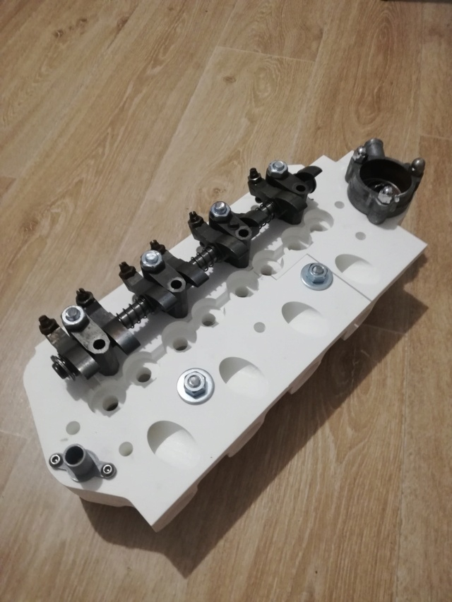
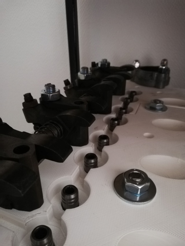
threaded rods are only used to hold 3d printed parts in place .
.
I won't be posting any photos of the chambers, final ducts or intake manifold for the time being. However, I hope you'll be interested in the project, and I'll be happy to talk about it.
Cheers
I don't know if this is the right place to talk about this project, but feel free to move it if you need to.
For those of you who don't know me, let me introduce myself quickly. I've been working on minis since I was twelve thirteen years old, and I've learnt a lot with these cars (carburetion, ignition, mechanical design, etc.).
Now, as an industrial engineering student, I wanted a project that was a bit more substantial and complete than what I'd been able to do up until now.
As some of you know, I have been working for a while time on the modelling of 8 port cylinder heads.
(as Trog was able to do with his cylinder head, thanks for sharing!)
The obejctive would be to revive the group two cylinder head.

So the first step was to read the documentation for this competition.


(source mk1 forum)
and finally, the regulations only require a few elements to be able to respond to this group's cylinder heads, which is good news!
After a year's research, I was able to start the work of modelling, understanding and analysing, which will enable this model to be competitive.
This work required a lot of time, a number of simulations, and also the development of a number of 3D printed prototypes.
The first of many steps was to determine the location of the important components of the cylinder head, i.e. the studs, the rocker arm passages, the coolant passages and the oil passages.

Once the elements had been designed, I printed them out to check the accuracy of the design.


Next step, the shape of the intake and exhaust ducts and the combustion chamber had to be determined.
Although as an engineering student I have access to interesting resources, but this part was extremely time-consuming.
The following images are not from the latest simalutions or designs (to protect my work I hope you'll understand). .
But they are useful for illustrating the post.
As you can see, I carried out a number of CFD simulations in order to optimise the flow of the cylinder head.
This was useful, because it's 'quite complicated'
The influence of the shape of the intake manifold on the flow is important, and simulations make it easier to interpret the results.


(non-contractual photo)
finally, after a few (many) hours, I managed to get a complete design

I've printed the whole thing out to check it.
but as it's a big piece, i had to do it in four parts, you can see the joins and the lack of detail, effectively it's a lightened version because concerning the time it's the equivalent of more than 4 days of printing 24/24.


threaded rods are only used to hold 3d printed parts in place
I won't be posting any photos of the chambers, final ducts or intake manifold for the time being. However, I hope you'll be interested in the project, and I'll be happy to talk about it.
Cheers
