1964 Rust project
-
baptiste
- Basic 850
- Posts: 68
- Joined: Wed May 27, 2015 5:32 pm
- Location: France
-
Frogeye61

- 998 Cooper
- Posts: 372
- Joined: Sun Mar 18, 2012 8:56 pm
- Location: Storkøbenhavn
Re: 1964 Rust project
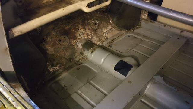
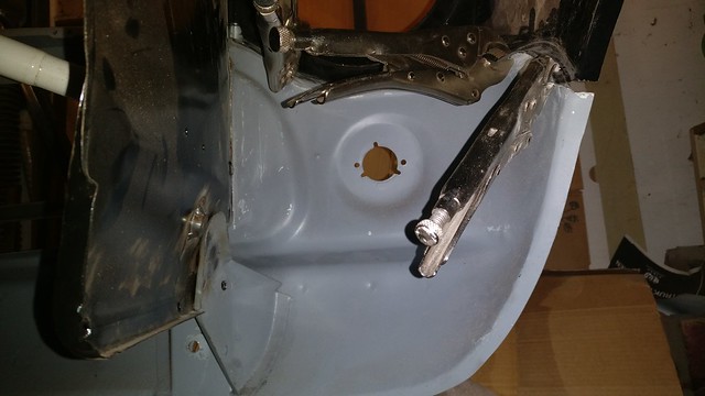
Tuesday, after cleaning up the foot panel around the magic wand shifter hole, Tim made a new cover which looks quite a bit better than the old patch that was there.
It still must be installed but not welded in as the old one was.
 IMG_20171004_073125 by frogeye61, on Flickr
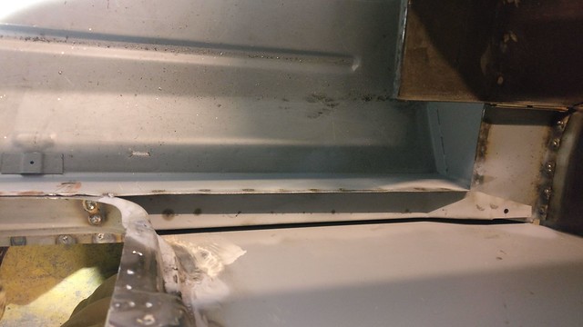
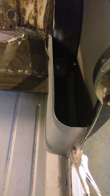
Meanwhile after painting inside the side panel with epoxy paint, I closed off the side bin bottom area, taking care to distance the rear plate to the side of the seat bottom by about 1.5mm. This gives clearance to slide in the parcel bin while I still have access to spot weld the three pieces together.
 IMG_20171003_205323r by frogeye61, on Flickr
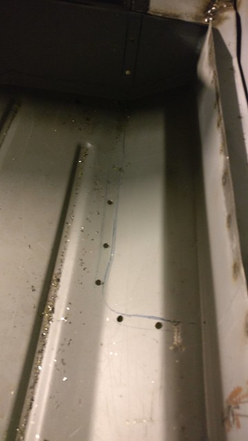
This was followed by again test fitting the side bin and marking the area where it mounts to the floor. Holes are drilled in this area for plug-welding from the bottom. This area is not accessible to spot weld with my type welder.
 IMG_20171003_213229 by frogeye61, on Flickr
It still must be installed but not welded in as the old one was.
IMG_20171004_073125 by frogeye61, on FlickrMeanwhile after painting inside the side panel with epoxy paint, I closed off the side bin bottom area, taking care to distance the rear plate to the side of the seat bottom by about 1.5mm. This gives clearance to slide in the parcel bin while I still have access to spot weld the three pieces together.
IMG_20171003_205323r by frogeye61, on FlickrThis was followed by again test fitting the side bin and marking the area where it mounts to the floor. Holes are drilled in this area for plug-welding from the bottom. This area is not accessible to spot weld with my type welder.
IMG_20171003_213229 by frogeye61, on Flickr-
Frogeye61
- 998 Cooper
- Posts: 372
- Joined: Sun Mar 18, 2012 8:56 pm
- Location: Storkøbenhavn
Re: 1964 Rust project
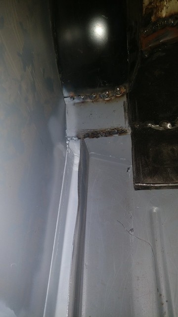
I finished up the right side bin bottom last weekend.
 IMG_20171004_180139 by frogeye61, on Flickr
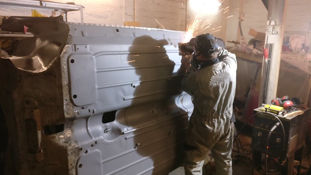
Tuesday evening we mounted the side bins and welded
 IMG_20171005_180434 by frogeye61, on Flickr
 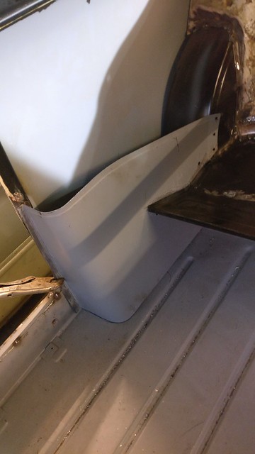 IMG_20171005_180440 by frogeye61, on Flickr
at first from the bottom and heal plate. Here we cleaned up the welds...
 IMG_20171010_191607 by frogeye61, on Flickr
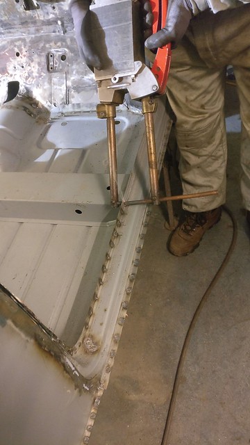
and then we spot welded all the pinch welds along the side bin to back seat bottom, plug welds to the rear inner fenders and spot welded the remaining door opening points. This also included the points where the support structure was fastened to the door opening and spot welding wasn't possible earlier.
 IMG_20171010_194552 by frogeye61, on Flickr
IMG_20171004_180139 by frogeye61, on FlickrTuesday evening we mounted the side bins and welded
IMG_20171005_180434 by frogeye61, on Flickr IMG_20171005_180440 by frogeye61, on Flickrat first from the bottom and heal plate. Here we cleaned up the welds...
IMG_20171010_191607 by frogeye61, on Flickrand then we spot welded all the pinch welds along the side bin to back seat bottom, plug welds to the rear inner fenders and spot welded the remaining door opening points. This also included the points where the support structure was fastened to the door opening and spot welding wasn't possible earlier.
IMG_20171010_194552 by frogeye61, on Flickr-
Frogeye61
- 998 Cooper
- Posts: 372
- Joined: Sun Mar 18, 2012 8:56 pm
- Location: Storkøbenhavn
Re: 1964 Rust project
Tuesday evening we spent cleaning up all welds on the inside of the cabin. Everything that had been welded and was a bit rough was re-welded as necessary and ground smooth. Special attention to the flanges for door seals and window rubbers.
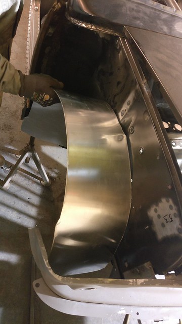
Also we made some front inner fender protectors from 2mm aluminium plate. It took quite a bit of time making the first protector from the older template I had made from 0.5mm alu plate. The original template was not stiff enough to hold shape and was therefore a bit oversize. We have some rubber seal extrusion which should work fine and holds superbly onto the 2mm plate. Photos of the test fit:
 IMG_20171017_211931 by frogeye61, on Flickr
 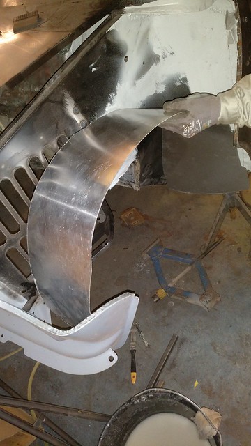 IMG_20171017_212025 by frogeye61, on Flickr
They will get rivet'ed on brackets which will be bolted onto existing points in the wheel well, and rubber sealing strip round the edges. The left side unit covers half the cooler opening and therefore has a very loose fit to the wing and front panel, allowing plenty of air flow, and no rubber seal in that area.
Also we made some front inner fender protectors from 2mm aluminium plate. It took quite a bit of time making the first protector from the older template I had made from 0.5mm alu plate. The original template was not stiff enough to hold shape and was therefore a bit oversize. We have some rubber seal extrusion which should work fine and holds superbly onto the 2mm plate. Photos of the test fit:
IMG_20171017_211931 by frogeye61, on Flickr IMG_20171017_212025 by frogeye61, on FlickrThey will get rivet'ed on brackets which will be bolted onto existing points in the wheel well, and rubber sealing strip round the edges. The left side unit covers half the cooler opening and therefore has a very loose fit to the wing and front panel, allowing plenty of air flow, and no rubber seal in that area.
-
Frogeye61
- 998 Cooper
- Posts: 372
- Joined: Sun Mar 18, 2012 8:56 pm
- Location: Storkøbenhavn
Re: 1964 Rust project
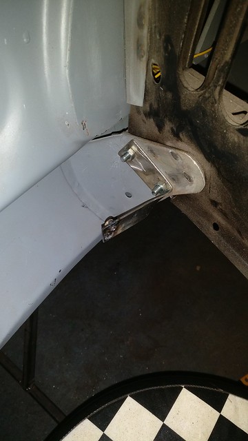
OK, I finally got a chance to make some brackets to mount the inner fenders. These are cut from 2mm steel plate and will receive epoxy paint. They are made with welded-on nuts so the inner fenders can be inserted from below. This stuff takes an incredible amount of time to do correctly.
 IMG_20171024_213020c by frogeye61, on Flickr
 IMG_20171024_213025 by frogeye61, on Flickr
 IMG_20171024_213032 by frogeye61, on Flickr
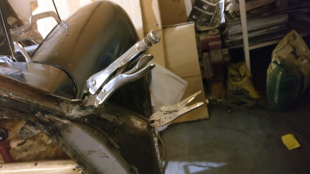
The inner fender units are now cut to the final shape and fitted with rubber extrusion sealing. Tested here with the front wing mounted with mole grips.
 IMG_20171024_210955 by frogeye61, on Flickr
View from below
 IMG_20171024_211020 by frogeye61, on Flickr
IMG_20171024_213020c by frogeye61, on FlickrIMG_20171024_213025 by frogeye61, on FlickrIMG_20171024_213032 by frogeye61, on FlickrThe inner fender units are now cut to the final shape and fitted with rubber extrusion sealing. Tested here with the front wing mounted with mole grips.
IMG_20171024_210955 by frogeye61, on FlickrView from below
IMG_20171024_211020 by frogeye61, on Flickr-
smithyrc30

- 1275 Cooper S
- Posts: 1383
- Joined: Thu Feb 05, 2015 8:40 am
Re: 1964 Rust project
Looking at the last picture, the front upper corner of the radiator air vent is now sealed so it goes into the area behind the headlight.
As this is the hottest part of the radiator (the hot water from the engine goes into that corner of the radiator) might it nut be better to reshape the aluminium to go above the radiator vents?
Trickier to make but might save you from over heating on a hot summer day.
As this is the hottest part of the radiator (the hot water from the engine goes into that corner of the radiator) might it nut be better to reshape the aluminium to go above the radiator vents?
Trickier to make but might save you from over heating on a hot summer day.
-
Frogeye61
- 998 Cooper
- Posts: 372
- Joined: Sun Mar 18, 2012 8:56 pm
- Location: Storkøbenhavn
Re: 1964 Rust project
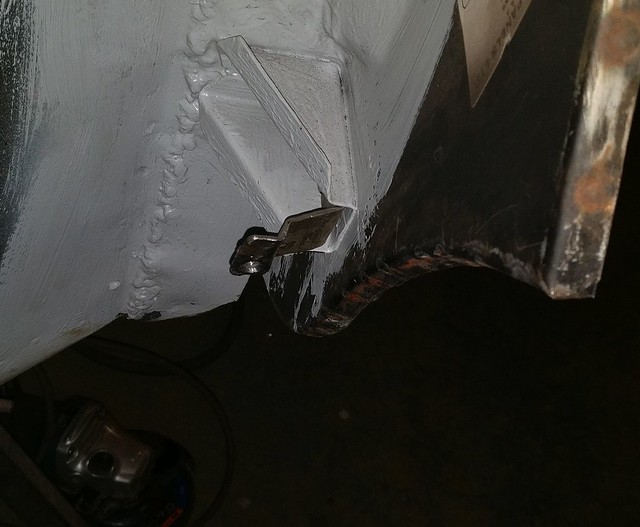
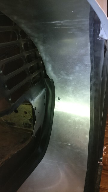
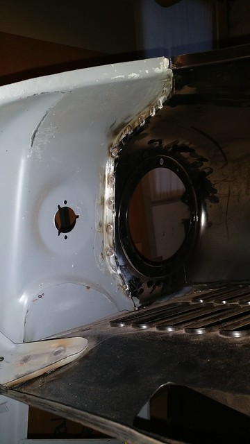
I did address this problem in my post from 18 Oct. There is a very loose fit between the inner wing and outer wing, allowing plenty of air flow. I did measure and calculate the open area between the inner wing and outer wing to be at least double the area of the covered part of the grille opening.
An I'm not sure what that means "hot summer." We don't have those here.
The free space between the wings and the protective panel, albeit without the rubber strip which stops above the front panel.
 IMG_20171024_203407c by frogeye61, on Flickr
An I'm not sure what that means "hot summer." We don't have those here.
The free space between the wings and the protective panel, albeit without the rubber strip which stops above the front panel.
IMG_20171024_203407c by frogeye61, on Flickr-
Frogeye61
- 998 Cooper
- Posts: 372
- Joined: Sun Mar 18, 2012 8:56 pm
- Location: Storkøbenhavn
Re: 1964 Rust project
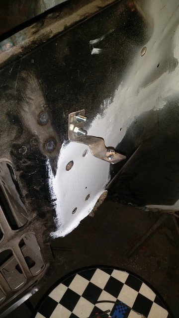
I was fortunate to find a bit of time during the past weekend to make up a set of mounting brackets for the right side inner wing protector.
Test fit without the wing mounted:
 IMG_20171029_155003 by frogeye61, on Flickr
Test fit without the wing mounted:
IMG_20171029_155003 by frogeye61, on Flickr-
Frogeye61
- 998 Cooper
- Posts: 372
- Joined: Sun Mar 18, 2012 8:56 pm
- Location: Storkøbenhavn
Re: 1964 Rust project
Last night now that all the inner protectors are finished, it was just a question of mounting the front wings.
All clamped in place and aligned, for which we took good time for perfect fit.
We had to close the bonnet and therefore had to mount the car on stands and remove the spit.
 IMG_20171031_193923 by frogeye61, on Flickr
 IMG_20171031_193931 by frogeye61, on Flickr
 IMG_20171031_193939 by frogeye61, on Flickr
Then spot welding. first a test spot on the bonnet gap area because we had to use the large c-grips there and couldn't close the bonnet. Not quite right, drilled out and did again.
BTW, the inner wings don't stay straight unless the wings are welded on. They had to be forced a bit to one side before welding.
After the top seam for which there is no image, down the side seams on both sides:
 IMG_20171031_200852 by frogeye61, on Flickr
Then the front seams from the inside. The car was turned on it's side for this - in with the spit, out with the stands.
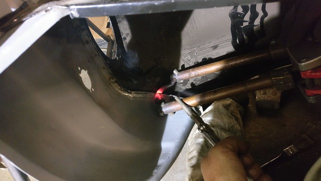 IMG_20171031_203755 by frogeye61, on Flickr
The welder is heavy!
Whooptie.
 IMG_20171031_203822 by frogeye61, on Flickr
Insted of rolling the car to the other side, we just worked above our heads and did the left side.
 IMG_20171031_204350 by frogeye61, on Flickr
Whooptie.
 IMG_20171101_072808 by frogeye61, on Flickr
And though it can't be seen so well, both wings are mounted and the entire front is straight.
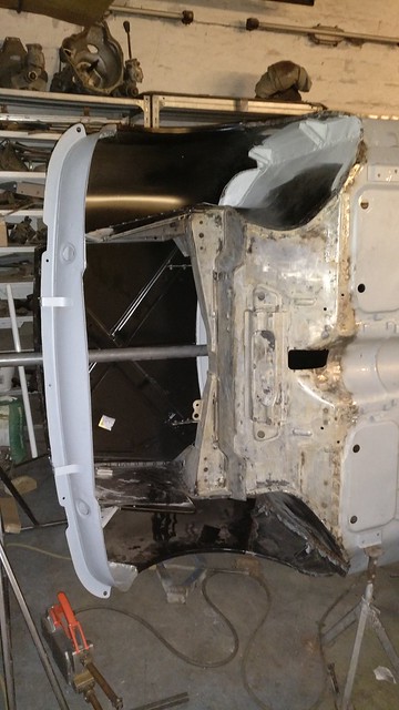 IMG_20171101_072724 by frogeye61, on Flickr
All clamped in place and aligned, for which we took good time for perfect fit.
We had to close the bonnet and therefore had to mount the car on stands and remove the spit.
IMG_20171031_193923 by frogeye61, on FlickrIMG_20171031_193931 by frogeye61, on FlickrIMG_20171031_193939 by frogeye61, on FlickrThen spot welding. first a test spot on the bonnet gap area because we had to use the large c-grips there and couldn't close the bonnet. Not quite right, drilled out and did again.
BTW, the inner wings don't stay straight unless the wings are welded on. They had to be forced a bit to one side before welding.
After the top seam for which there is no image, down the side seams on both sides:
IMG_20171031_200852 by frogeye61, on FlickrThen the front seams from the inside. The car was turned on it's side for this - in with the spit, out with the stands.
IMG_20171031_203755 by frogeye61, on FlickrThe welder is heavy!
Whooptie.
IMG_20171031_203822 by frogeye61, on FlickrInsted of rolling the car to the other side, we just worked above our heads and did the left side.
IMG_20171031_204350 by frogeye61, on FlickrWhooptie.
IMG_20171101_072808 by frogeye61, on FlickrAnd though it can't be seen so well, both wings are mounted and the entire front is straight.
IMG_20171101_072724 by frogeye61, on Flickr-
Daz1968
- 1275 Cooper S
- Posts: 1440
- Joined: Sat Dec 27, 2014 1:41 pm
- Location: Oldbury west midlands
-
JC T ONE
- 1275 Cooper S
- Posts: 3180
- Joined: Fri Aug 13, 2010 5:25 am
- Location: Denmark
Re: 1964 Rust project
Nice to see a pair of innerwings, not only do they protect, they also reduce the noise lewel a lot 
-
Frogeye61
- 998 Cooper
- Posts: 372
- Joined: Sun Mar 18, 2012 8:56 pm
- Location: Storkøbenhavn
Re: 1964 Rust project
I appreciate your point and admit I thought about doing that. Based on information from Georg at ÅKM Racing, one could do exactly that using Heritage or some M-Machine panels, but not on lesser expensive aftermarket panels. Having many cheaper panels, I simply mounted the front panel to the subframe and assumed it would therefore be correct. This may also be mistaken, but at least the subframe should fit. The difficult welding therefore had to be done.Daz1968 wrote:I cheated and spot welded wings to front panel off the car,
-
Frogeye61
- 998 Cooper
- Posts: 372
- Joined: Sun Mar 18, 2012 8:56 pm
- Location: Storkøbenhavn
Re: 1964 Rust project
Nice having a Sunday to work alone in the garage.
Saturday, since I am finished with the spot welder, I took it back to the garage club in Lyngby. I've only borrowed it for 9 months or so. But now there are all those small edges and corners that need finishing. Like these;
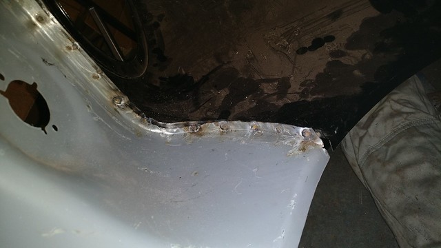
Front wings to front panel;
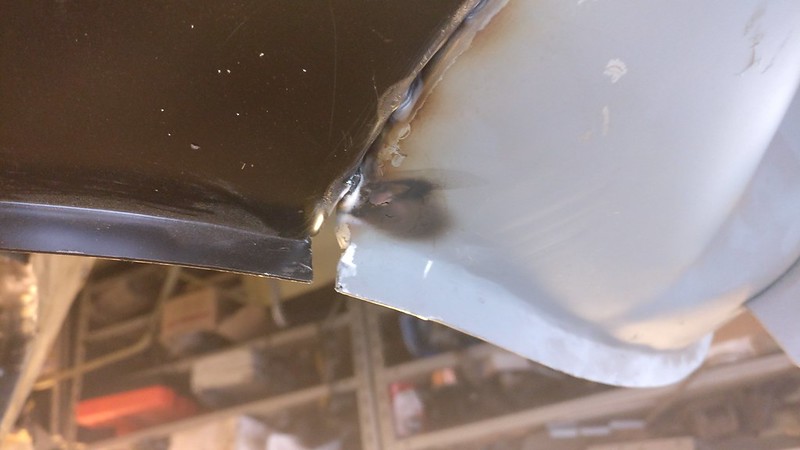 IMG_20171105_123352 by frogeye61, on Flickr
 IMG_20171105_134707 by frogeye61, on Flickr
Windscreen surround to roof gutter:
 IMG_20171105_123343 by frogeye61, on Flickr
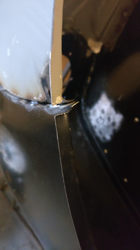
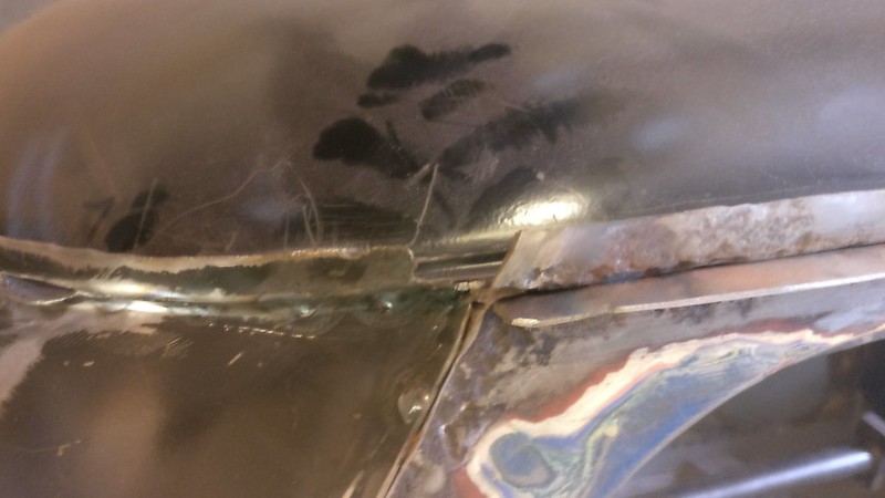
Rear wing and inner wing to lower panel;
' IMG_20171105_141637 by frogeye61, on Flickr
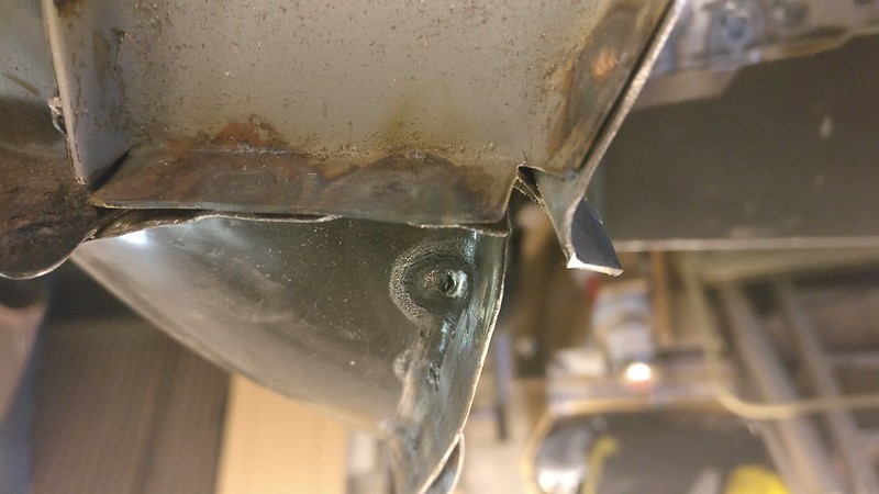 IMG_20171105_133004 by frogeye61, on Flickr
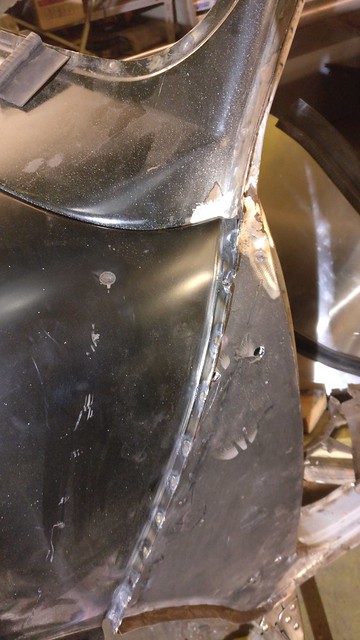
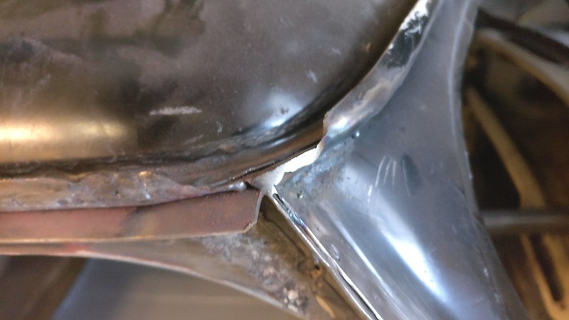
Rear wing corner to inner wing;
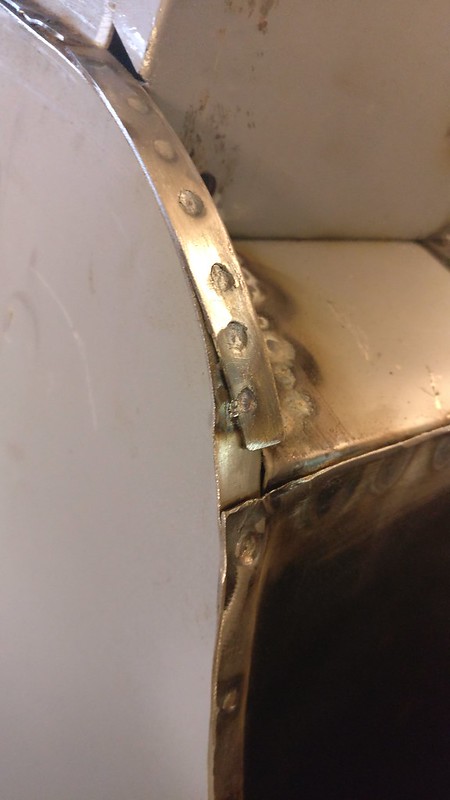 IMG_20171105_133919 by frogeye61, on Flickr
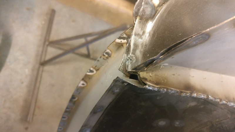
Back panel to roof gutter;
 IMG_20171105_123337 by frogeye61, on Flickr
I'm sure I have lots more boring pictures of these small welds but suffice to say they all got welded up today.
Example;
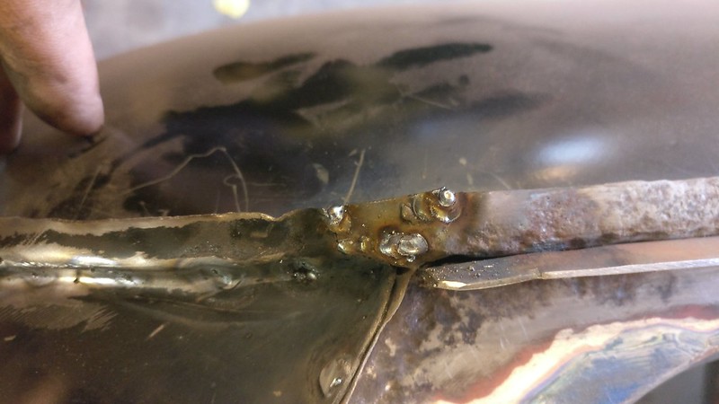 IMG_20171105_132343 by frogeye61, on Flickr
 IMG_20171105_132901 by frogeye61, on Flickr
Saturday, since I am finished with the spot welder, I took it back to the garage club in Lyngby. I've only borrowed it for 9 months or so. But now there are all those small edges and corners that need finishing. Like these;
Front wings to front panel;
IMG_20171105_123352 by frogeye61, on FlickrIMG_20171105_134707 by frogeye61, on FlickrWindscreen surround to roof gutter:
IMG_20171105_123343 by frogeye61, on FlickrRear wing and inner wing to lower panel;
'
IMG_20171105_141637 by frogeye61, on FlickrIMG_20171105_133004 by frogeye61, on FlickrRear wing corner to inner wing;
IMG_20171105_133919 by frogeye61, on FlickrBack panel to roof gutter;
IMG_20171105_123337 by frogeye61, on FlickrI'm sure I have lots more boring pictures of these small welds but suffice to say they all got welded up today.
Example;
IMG_20171105_132343 by frogeye61, on FlickrIMG_20171105_132901 by frogeye61, on Flickr-
trevorhp

- 1275 Cooper S
- Posts: 929
- Joined: Thu Feb 17, 2011 9:38 pm
- Location: Taunton Somerset UK Formerly Kingswinford
- Has thanked: 16 times
- Been thanked: 9 times
- Contact:
Re: 1964 Rust project
Nice work
Looking forward to the next pictures
Looking forward to the next pictures
Last edited by trevorhp on Fri Nov 10, 2017 10:06 pm, edited 1 time in total.
"Ambition: the first step on the road to disappointment" Homer. J. Simpson
"Disappointment: the first step on the road to enlightenment" Buddha
"Enlightenment: the first step on the road to ambition" Dalai Lama
No point in hoping to go to Heaven...... I won't know anyone there.
KDK 320F
HDK 443E
DJJ 226H
TFD 47G
PKV 375
I x 1967 originally Red since 1968 Blue,Ex-Race Cooper S Bodyshell only have Commission plate as ID.
1 x chassis 007 1967 Cox GTM
-
Andrew1967

- 1275 Cooper S
- Posts: 7919
- Joined: Thu Jun 24, 2010 6:35 pm
- Location: Usually in my garage on the east coast of Norfolk, UK
- Been thanked: 9 times
Re: 1964 Rust project
Brilliant work - just about to start pulling my S apart and as said before, this thread is going to be extremely helpful to me. Keep it going
-
Frogeye61
- 998 Cooper
- Posts: 372
- Joined: Sun Mar 18, 2012 8:56 pm
- Location: Storkøbenhavn
Re: 1964 Rust project
Thank you Andrew. That's exactly my motivation why I want to put up a bunch of boring, but helpful pictures.
-
Tim
- 1275 Cooper S
- Posts: 1291
- Joined: Thu Jun 24, 2010 11:55 pm
- Location: Tasmania, Australia
- Has thanked: 4 times
- Been thanked: 22 times
Re: 1964 Rust project
Not boring. I'm following along in awe of the quality and quantity of the work that is being done!
Tim
Tim
1951 Morris Commercial J Type Van
1955 BSA C11G
1961 Morris Mini Traveller
1969 Triumph TR6R
1977 Leyland Moke Californian
1955 BSA C11G
1961 Morris Mini Traveller
1969 Triumph TR6R
1977 Leyland Moke Californian
-
Frogeye61
- 998 Cooper
- Posts: 372
- Joined: Sun Mar 18, 2012 8:56 pm
- Location: Storkøbenhavn
Re: 1964 Rust project
Another lovely Tuesday evening! Peter actually went home early citing headache from all the noise. We had two angle grinders running most of the time. Only one on the Mini, the other on a motorcycle sidecar.
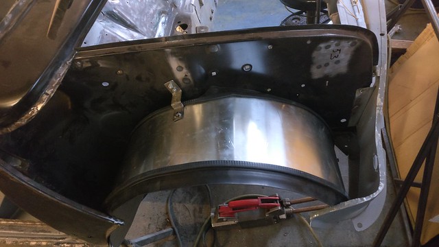
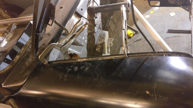
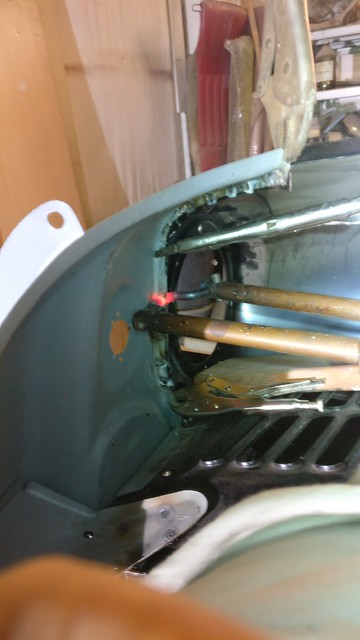
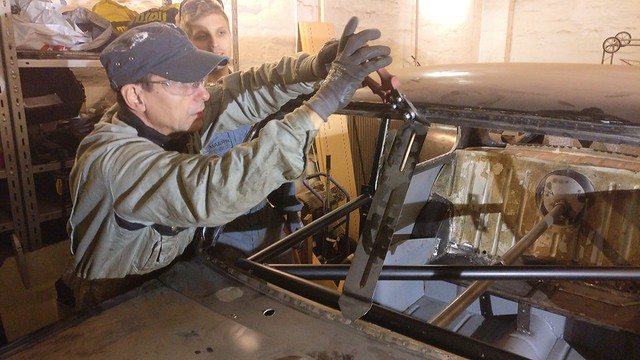
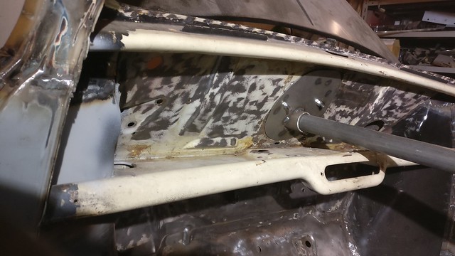
However before all the noise, we thought it would be nice with a test fit of the Safety Devices rear bar with cross-brace.
 IMG_20171107_175353 by frogeye61, on Flickr
Did anybody mention that theses are quite impossible to install in a completed car. And it doesn't have anything to do with the spit being in place. The four bottom feet of the are all too wide to fit past the B-post, in any possibility or any position-gyration.
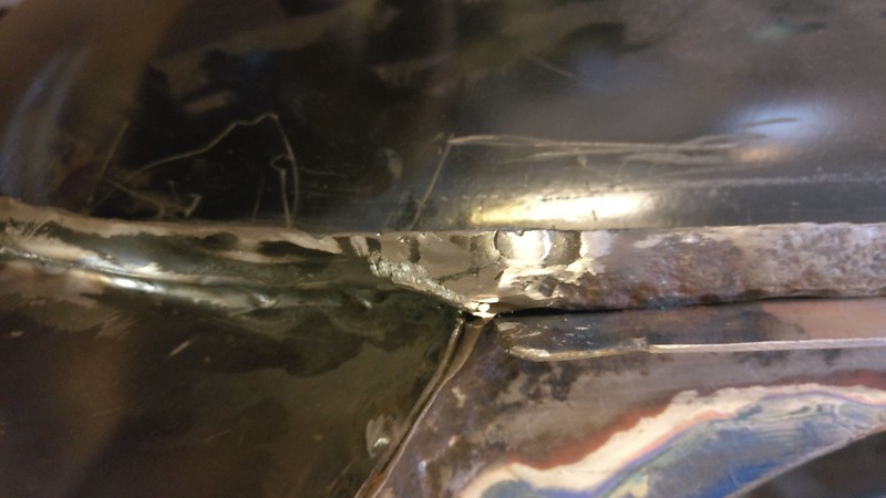
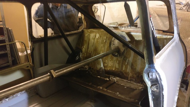
In the end it went in feet first. We used a rope to hold the forward feet together about 2 cm from rest point, and a cable-pull to pull the rear feet together nearly 4 cm. I suppose it would have been easier if there were no side bins but alas there are!
The front feet must pass between the side bins and door latch while the rear feet must pass further up on the B-post. This required violent compression of the rear bar's width. We also had to remove the windshield spacer which for some reason we have resisted. This implies that if it is done in a completed car, the windshield should be removed. This to allow the bar to go far enough forward that the front feet can go over the side bins.
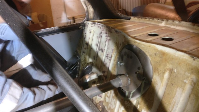
 IMG_20171107_180124 by frogeye61, on Flickr
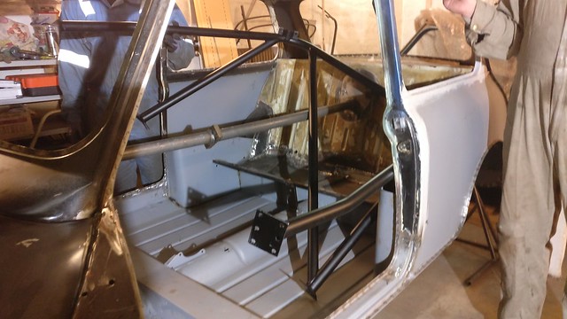
Well, it's finally in place. It's a good thing we did it before paint as it would have scratched the heck out of the interior. We now have to put the mounting plates in, weld and epoxy paint before finally bolting the bar in place down INSIDE the side bins!. I guess in the end everything will be painted one colour. (Don't forget to tape the approval sticker before painting)
 IMG_20171107_181531 by frogeye61, on Flickr
OK, so the angle grinder stuff.
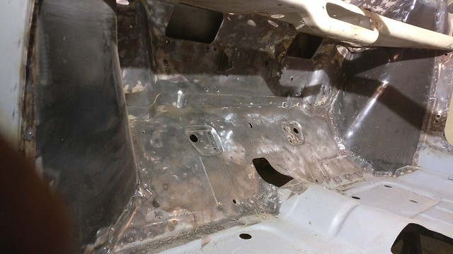 IMG_20171107_202355 by frogeye61, on Flickr
These panels were covered with glue and insulation fibers.
 IMG_20171107_202400 by frogeye61, on Flickr
Also the back seat. But they are all cleaned up now, awaiting sanding before epoxy primer.
 IMG_20171107_202405 by frogeye61, on Flickr
However before all the noise, we thought it would be nice with a test fit of the Safety Devices rear bar with cross-brace.
IMG_20171107_175353 by frogeye61, on FlickrDid anybody mention that theses are quite impossible to install in a completed car. And it doesn't have anything to do with the spit being in place. The four bottom feet of the are all too wide to fit past the B-post, in any possibility or any position-gyration.
In the end it went in feet first. We used a rope to hold the forward feet together about 2 cm from rest point, and a cable-pull to pull the rear feet together nearly 4 cm. I suppose it would have been easier if there were no side bins but alas there are!
The front feet must pass between the side bins and door latch while the rear feet must pass further up on the B-post. This required violent compression of the rear bar's width. We also had to remove the windshield spacer which for some reason we have resisted. This implies that if it is done in a completed car, the windshield should be removed. This to allow the bar to go far enough forward that the front feet can go over the side bins.
IMG_20171107_180124 by frogeye61, on FlickrWell, it's finally in place. It's a good thing we did it before paint as it would have scratched the heck out of the interior. We now have to put the mounting plates in, weld and epoxy paint before finally bolting the bar in place down INSIDE the side bins!. I guess in the end everything will be painted one colour. (Don't forget to tape the approval sticker before painting)
IMG_20171107_181531 by frogeye61, on FlickrOK, so the angle grinder stuff.
IMG_20171107_202355 by frogeye61, on FlickrThese panels were covered with glue and insulation fibers.
IMG_20171107_202400 by frogeye61, on FlickrAlso the back seat. But they are all cleaned up now, awaiting sanding before epoxy primer.
IMG_20171107_202405 by frogeye61, on Flickr-
rich@minispares.com

- 1275 Cooper S
- Posts: 6806
- Joined: Thu Aug 08, 2013 3:16 pm
- Been thanked: 2 times
Re: 1964 Rust project
you don't need to remove any glass to get a safety devices cage into a car
you just need to pull the legs in with a cargo strap to wriggle it into the back, once its in, remove the straps.
I then use a porta pack to push the legs out to that they are all equally spaced (normally only have to do the two rear most ones) whilst I drill the holes, so its all nice and neat.
there should be no 'preload' or straining required to fit the bolts once the holes are drilled (bar a little bit of jiggling)
when I refit them (once car is painted) I make sure that I tape all the b pillers and the cant rails that are under the side windows, and wrap bubble wrap around all four feet to avoid scratches.
my race car is a real swine to get the cage in as its an early shell with the tapered sill closing panels in the rear pockets, so there isn't a lot of space to get the legs into place.
to be fair, in your photo, it would have been a struggle with the spit bar still fitted to the car, any wonder you struggled!
-
baptiste
- Basic 850
- Posts: 68
- Joined: Wed May 27, 2015 5:32 pm
- Location: France