Mhuffy The Traveller.
-
JC T ONE
- 1275 Cooper S
- Posts: 3180
- Joined: Fri Aug 13, 2010 5:25 am
- Location: Denmark
Re: Mhuffy The Traveller.
Why not cut the pipe, where the Beam sit, and weld on a S shaped piece.
This way the muffler ends up "inline" with the car, so it clears the well for the spare wheel.
This way the muffler ends up "inline" with the car, so it clears the well for the spare wheel.
- Dr.Mabo
- 998 Cooper
- Posts: 500
- Joined: Wed Jun 27, 2012 1:05 pm
- Location: Germany
- Been thanked: 6 times
Re: Mhuffy The Traveller.
I have a RC40 mounted to my Traveller. I didn't modify the spare wheel well to get more clearance to the road I rather modified the RC40 rear box.
As the spare wheel well is part of the body and the exhaust is changeable I thought thats the better way.
Modifying the rear box was just with a hugh and heavy plasic hammer, while I placed the box on a woodn surface.
This is working fine since about ten years and is not noticable from underneath.
so long
the doc
-
surfblue63
Re: Mhuffy The Traveller.
I have the same system on my Traveller, but I have a freeflow manifold. To get more clearance of the spare wheel well the silencer was turned, however, this lowers the tailpipe and makes it point downwards.


-
InimiaD
- 1275 Cooper S
- Posts: 1526
- Joined: Thu Jul 01, 2010 11:20 pm
- Location: West of Offas Dyke.
Re: Mhuffy The Traveller.
Thanks for the replies gents.
A few ideas to mull over. I had thought of chopping a section out of the rear silencer and welding in a new section which sounds drastic, but will give me the needed clearance and the rear box will fit in the space nicely.
The Docs' suggestion would be an easier option and I have a good selection of persuaders.
An associate has a Play Mini system on his traveller, but the tail pipe extends out to the left corner. Doesn't look right at all.
It seems to me that the exhaust manufacturers, Maniflow etc, have missed a trick here. It can't be that difficult to design a decent sports exhaust system for a Mini estate that fits snugly without having to resort to drastic chopping and hammering.
-
1071 S
- 1275 Cooper S
- Posts: 916
- Joined: Sun Jun 27, 2010 8:44 am
- Location: Southern Tablelands (Oz)
Re: Mhuffy The Traveller.
RC40 only requires a few whacks with the dead blow hammer on the spare wheel well. If that 's ever a problem I shall just whack the same area from the inside.
Cheers, Ian
Cheers, Ian
-
InimiaD
- 1275 Cooper S
- Posts: 1526
- Joined: Thu Jul 01, 2010 11:20 pm
- Location: West of Offas Dyke.
Re: Mhuffy The Traveller.
Time to get down and dirty in the workshop again, now that I've pacified her indoors with some jobs around the grounds etc. 
Some of you may remember my attempts to try out another engine mounting system with some home made brackets etc.
The time has come to get on with this job so I can fit the refurbed front subby to the Woody.
In a nutshell I have abandoned the previous attempt and started making a newer version which will move the new mounting closer to the corner of the subframe where the load will be better supported.
Firstly, I made a new bracket which fixes to the side of the engine end plate.
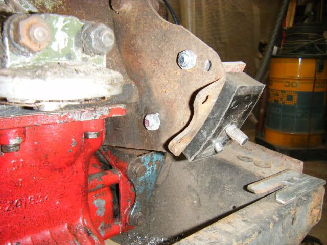
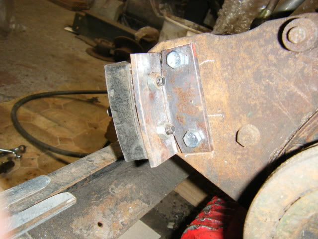
With that sorted I then played with some box section which was attached to the plate that the rubber engine mount sits in.
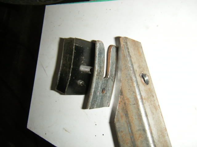
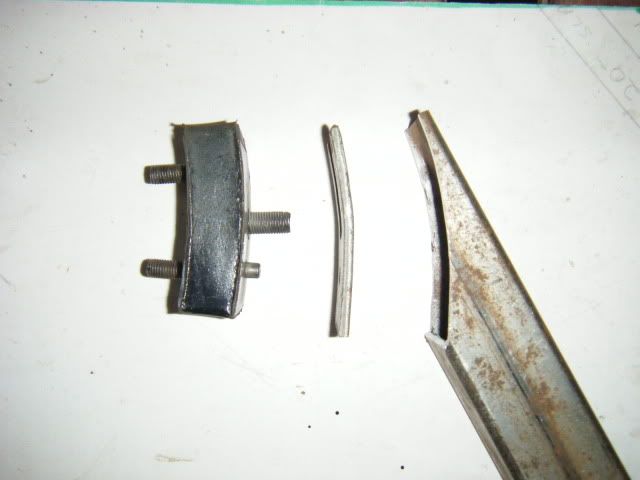
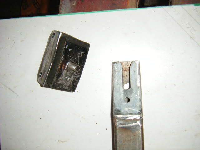
The aim is to attach the box section to the leading edge of the subframe using bolts and captive nuts. This MK2 version should be a lot stronger and ensure there is no side movement of the engine.
Next stage is to cut the box section to fit, add some captive nuts, a side bracket and and and,,,,,,,,,,

Some of you may remember my attempts to try out another engine mounting system with some home made brackets etc.
The time has come to get on with this job so I can fit the refurbed front subby to the Woody.
In a nutshell I have abandoned the previous attempt and started making a newer version which will move the new mounting closer to the corner of the subframe where the load will be better supported.
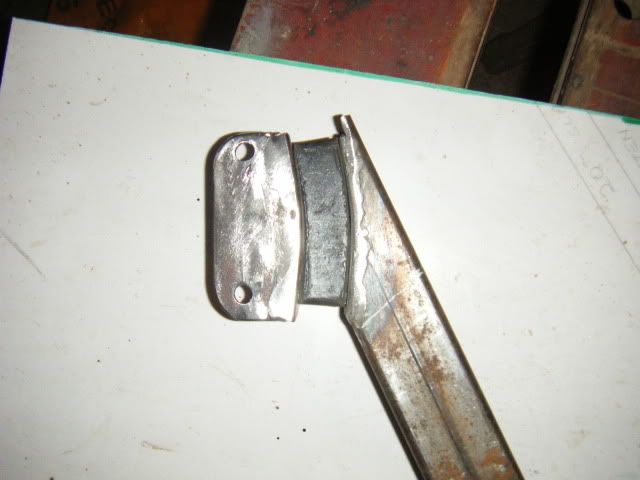
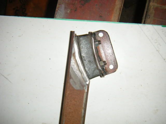
Firstly, I made a new bracket which fixes to the side of the engine end plate.


With that sorted I then played with some box section which was attached to the plate that the rubber engine mount sits in.


The aim is to attach the box section to the leading edge of the subframe using bolts and captive nuts. This MK2 version should be a lot stronger and ensure there is no side movement of the engine.
Next stage is to cut the box section to fit, add some captive nuts, a side bracket and and and,,,,,,,,,,


- sclemow
- 998 Cooper
- Posts: 337
- Joined: Thu Jun 24, 2010 1:02 pm
- Location: Bristol, UK
Re: Mhuffy The Traveller.
Have you thought about giving maniflow a call and asking them to make up a slightly different shape mid pipe?
I doubt it would cost much and I've always found them very helpful with stuff like this.
Great work BTW I've really enjoyed this thread, wish I had those kind of tinwork skills!
S
I doubt it would cost much and I've always found them very helpful with stuff like this.
Great work BTW I've really enjoyed this thread, wish I had those kind of tinwork skills!
S
-
InimiaD
- 1275 Cooper S
- Posts: 1526
- Joined: Thu Jul 01, 2010 11:20 pm
- Location: West of Offas Dyke.
Re: Mhuffy The Traveller.
I've got a pic of a standard zorzt system for an Estate and from the pic I can see that the pipe section is S shaped so the rear silencer clears the tyre well. If I applied that principle to the system I have now I would need to chop the rear tailpipe to get the "angle" correct.sclemow wrote:Have you thought about giving maniflow a call and asking them to make up a slightly different shape mid pipe?
I doubt it would cost much and I've always found them very helpful with stuff like this.
Great work BTW I've really enjoyed this thread, wish I had those kind of tinwork skills!
S
It's all a bit frustrating because the exhaust system is basically all saloon except for the longer front pipe and stainless extension on the rear of the back box.
Thanks for the input though, and I might just follow up your suggestion, after I've thrown all the toys out of the pram.
-
JC T ONE
- 1275 Cooper S
- Posts: 3180
- Joined: Fri Aug 13, 2010 5:25 am
- Location: Denmark
-
InimiaD
- 1275 Cooper S
- Posts: 1526
- Joined: Thu Jul 01, 2010 11:20 pm
- Location: West of Offas Dyke.
Re: Mhuffy The Traveller.
Thank You Jens.JC T ONE wrote:Nice engine mounts
Next job was to manipulate a plate for the box section to sit on and help spread the load. Added some captive nuts, 2 for the lower web and 1 for the front. Should be enough, the ADO 16 only had three bolts securing the front engine mount to the subframe.
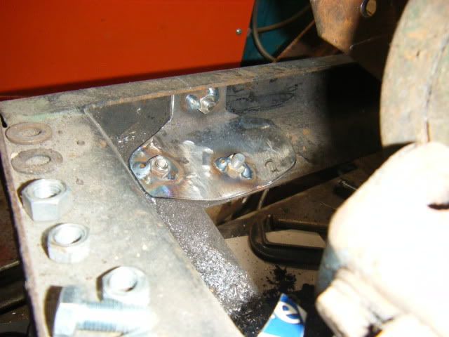
Took an age to get the box section to line up, but got there eventually.
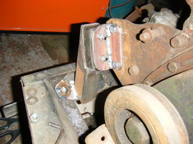
In position and tacked onto the support plate.
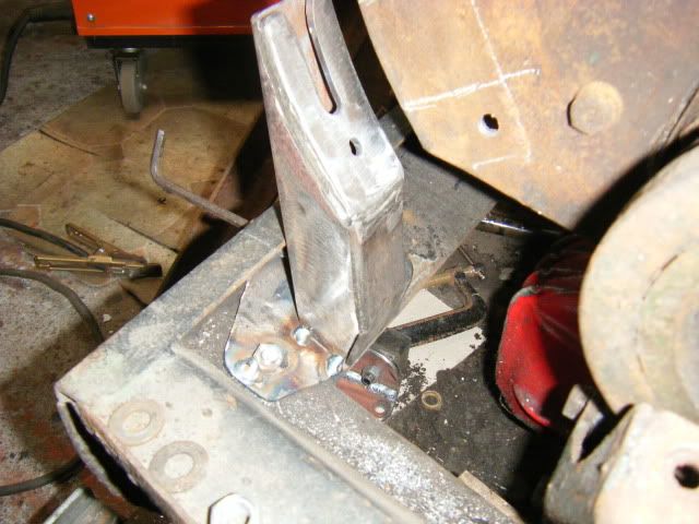
Nearly there.
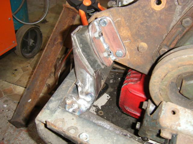
In position.
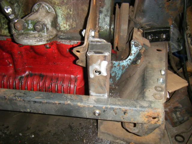
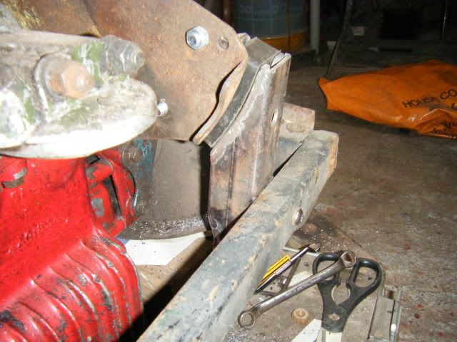
Fairly pleased with the end product. At least it is removable if needed to carry out any maintenance in that area.
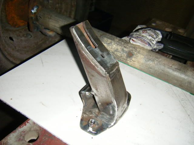
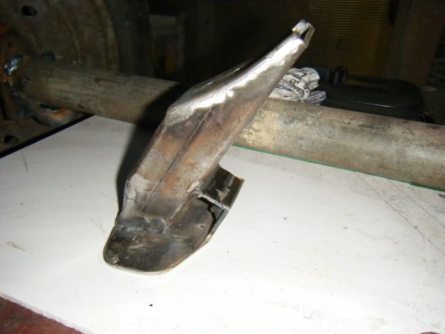
The rear mount is next on the horizon. Bugger all space to fabricate in situ though.
-
InimiaD
- 1275 Cooper S
- Posts: 1526
- Joined: Thu Jul 01, 2010 11:20 pm
- Location: West of Offas Dyke.
Re: Mhuffy The Traveller.
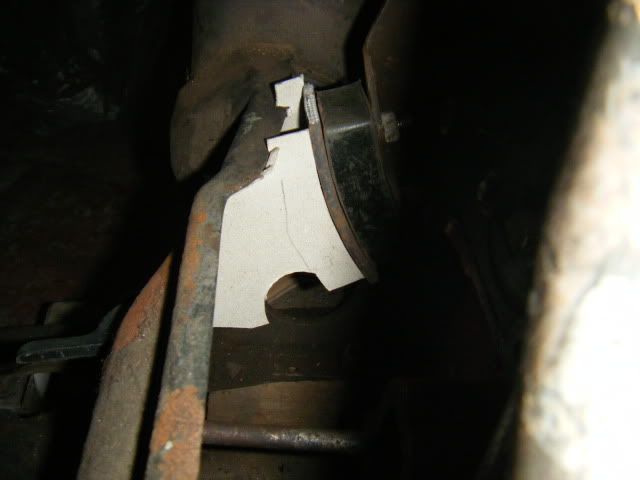
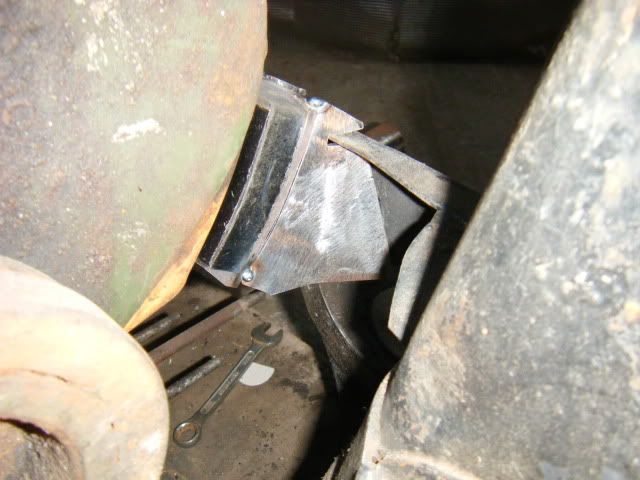
Onto the rear mount.
Little room to play with.
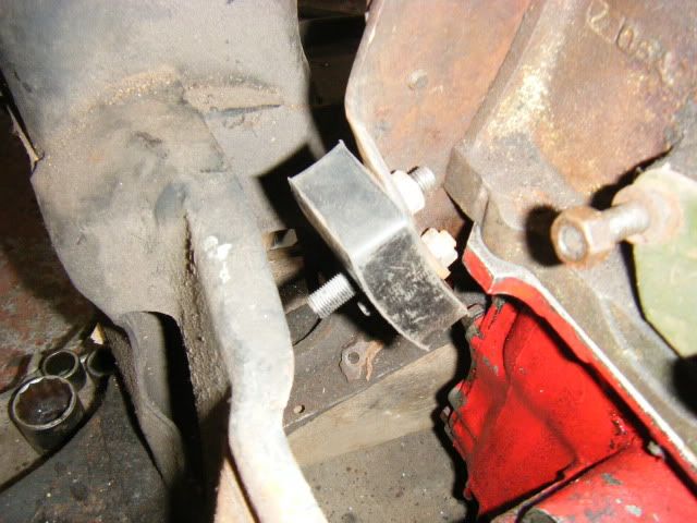
,,,,,,So had to resort to the "card template" process.
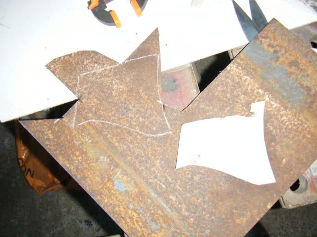
Transferred onto some steel plate.
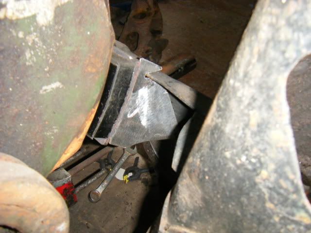
After what seemed like an age the webs were eventually fettled to fit snugly and then tack welded to to the mounting carrier.
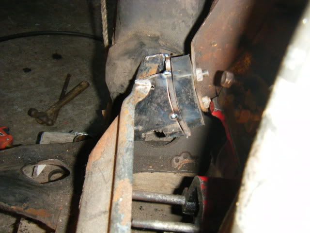
With that done, next job was to transfer the "donkey" engine into the "new" subframe.
Little room to play with.

,,,,,,So had to resort to the "card template" process.

Transferred onto some steel plate.

After what seemed like an age the webs were eventually fettled to fit snugly and then tack welded to to the mounting carrier.


With that done, next job was to transfer the "donkey" engine into the "new" subframe.
-
36inter
- 998 Cooper
- Posts: 506
- Joined: Sun Jul 04, 2010 8:15 pm
Re: Mhuffy The Traveller.
Thats good work, same same as I did and your engine will just not rock at all and be so nice to drive.
Keep the pic's coming.
Pete
Keep the pic's coming.
Pete
-
InimiaD
- 1275 Cooper S
- Posts: 1526
- Joined: Thu Jul 01, 2010 11:20 pm
- Location: West of Offas Dyke.
Re: Mhuffy The Traveller.
Thank you Pete. First signs are encouraging. There's hardly any movement with the engine after being assaulted with a crowbar. 
Transfer time. The "donkey" engine being placed in it's temporary home.
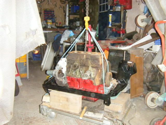
I foolishly thought that it would be a simple case of just marking through the base of front mount and drilling some holes.
NOT
The difference in shape of the 2 subframes was very obvious when I tried to line up the front mount especially the front rail, which was a different profile
I had no choice but to re-align the mounting holes on the end plate which was easier than reworking the mount.
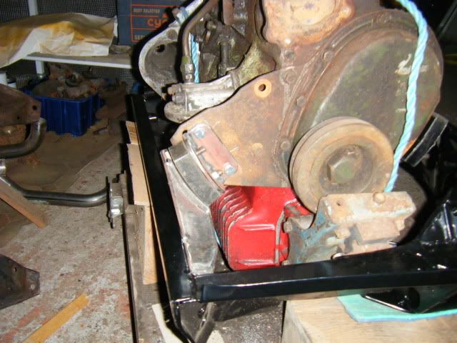
In hindsight I should have done all the fabrication work for the new mounts on the actual subframe I was going to use.
Ah well, live and learn eh.
Transfer time. The "donkey" engine being placed in it's temporary home.

I foolishly thought that it would be a simple case of just marking through the base of front mount and drilling some holes.
NOT
The difference in shape of the 2 subframes was very obvious when I tried to line up the front mount especially the front rail, which was a different profile
I had no choice but to re-align the mounting holes on the end plate which was easier than reworking the mount.

In hindsight I should have done all the fabrication work for the new mounts on the actual subframe I was going to use.
Ah well, live and learn eh.
-
JC T ONE
- 1275 Cooper S
- Posts: 3180
- Joined: Fri Aug 13, 2010 5:25 am
- Location: Denmark
Re: Mhuffy The Traveller.
Looking very effective & strong 
will you keep the standard rubber mount under the radiator ?
will you keep the standard rubber mount under the radiator ?
-
InimiaD
- 1275 Cooper S
- Posts: 1526
- Joined: Thu Jul 01, 2010 11:20 pm
- Location: West of Offas Dyke.
Re: Mhuffy The Traveller.
Needless to say the rear mount didn't sit correctly in this subby either, so that needed unpicking into it's component parts and coerced into fitting snugly.
With everything lined up the carrier was tack welded (again) to the webs.
The engine was then lifted out of the subframe so I could get at the area where the rear mount was going to be welded to.
The new powder coating was ground off, ( yes i know, sacrilege) and then the engine was thrown back in, but not before I had fully welded the webs to the carrier.
After double checking that everything lined up I took a deep breath, closed my eyes and tacked the rear mount in place.
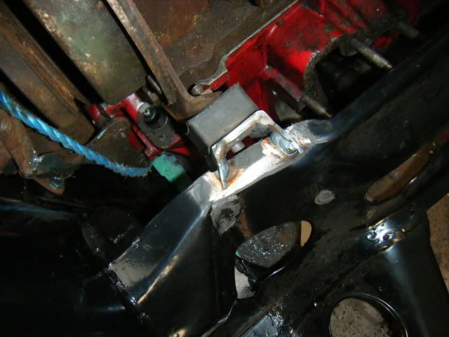
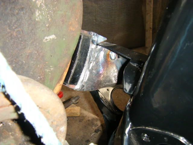
The engine was lifted out again so i could fully weld the whole mount into place.
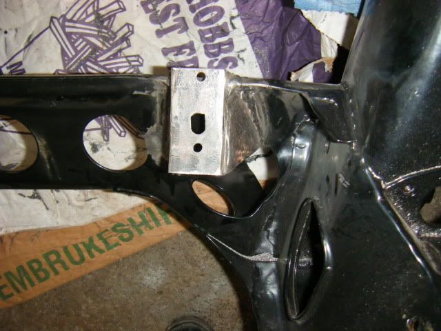
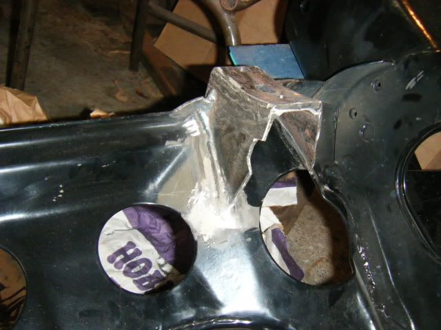
In answer to your question Jens,,,,,,,
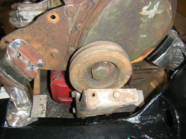
The engine sitting on it's new mountings minus the standard mount under the rad end.
I don't think the standard mount is needed, but it would be handy to have in case of emergencies or when my new engine mounts fail due to the abuse from a screaming 848cc motor.
With everything lined up the carrier was tack welded (again) to the webs.
The engine was then lifted out of the subframe so I could get at the area where the rear mount was going to be welded to.
The new powder coating was ground off,
After double checking that everything lined up I took a deep breath, closed my eyes and tacked the rear mount in place.


The engine was lifted out again so i could fully weld the whole mount into place.


In answer to your question Jens,,,,,,,

The engine sitting on it's new mountings minus the standard mount under the rad end.
I don't think the standard mount is needed, but it would be handy to have in case of emergencies or when my new engine mounts fail due to the abuse from a screaming 848cc motor.
-
JC T ONE
- 1275 Cooper S
- Posts: 3180
- Joined: Fri Aug 13, 2010 5:25 am
- Location: Denmark
Re: Mhuffy The Traveller.
InimiaD wrote: In answer to your question Jens,,,,,,,
The engine sitting on it's new mountings minus the standard mount under the rad end.
I don't think the standard mount is needed, but it would be handy to have in case of emergencies or when my new engine mounts fail due to the abuse from a screaming 848cc motor.
Looking good, now you just need to trim the plate behind the timing chain.
The engine mounts in my car are the original ones (nice & soft) and they still hold together
- Vegard
- 1275 Cooper S
- Posts: 2042
- Joined: Mon Jun 28, 2010 1:33 pm
- Location: Norway
- Contact:
-
InimiaD
- 1275 Cooper S
- Posts: 1526
- Joined: Thu Jul 01, 2010 11:20 pm
- Location: West of Offas Dyke.
Re: Mhuffy The Traveller.
I'm trying to minimize engine rock without having to resort to solid engine mounts.
The reason I need to reduce engine movement is because the gear stick / rod change will be inside the car and will be rubber mounted.
Less engine rock equals less strain on the gear change mounts.
The reason I need to reduce engine movement is because the gear stick / rod change will be inside the car and will be rubber mounted.
Less engine rock equals less strain on the gear change mounts.
-
JC T ONE
- 1275 Cooper S
- Posts: 3180
- Joined: Fri Aug 13, 2010 5:25 am
- Location: Denmark
Re: Mhuffy The Traveller.
Hej Vegard,Vegard wrote:Could I ask, what are you trying to achieve with these mounts?
As Inimia already posted does these 1100/1300 type engine mounts keep the engine in place.
Plus they give a MUCH more pleasant & silent drive
The reason to why there is a HUGE advantage with this setup, is that it lines up with the center of the crankshaft = tourqe point,
which means you dont get those hard movements when you let go of the throttle, and then press it down again.
If you ever come by = Snekkersten (Elsinore Denmark) I will take you for a spin, so you can feel the difference.
Jens Christian
-
36inter
- 998 Cooper
- Posts: 506
- Joined: Sun Jul 04, 2010 8:15 pm
Re: Mhuffy The Traveller.
I have to say the benefit that this type of mounting gives is huge, massive. For me it transformed the drive of the car, if JC's is anything like the same you need to drive it to understand how big an improvement it is.
Pete
Pete