8 ports cylinder Head project
-
- Basic 850
- Posts: 68
- Joined: Wed May 27, 2015 5:32 pm
- Location: France
8 ports cylinder Head project
Hi everyone,
I don't know if this is the right place to talk about this project, but feel free to move it if you need to.
For those of you who don't know me, let me introduce myself quickly. I've been working on minis since I was twelve thirteen years old, and I've learnt a lot with these cars (carburetion, ignition, mechanical design, etc.).
Now, as an industrial engineering student, I wanted a project that was a bit more substantial and complete than what I'd been able to do up until now.
As some of you know, I have been working for a while time on the modelling of 8 port cylinder heads.
(as Trog was able to do with his cylinder head, thanks for sharing!)
The obejctive would be to revive the group two cylinder head.
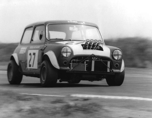
So the first step was to read the documentation for this competition.
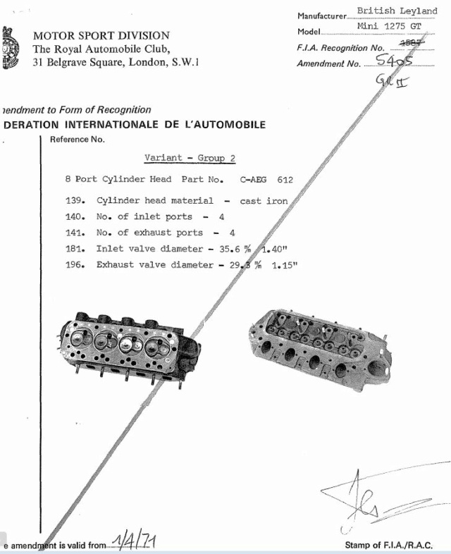
(source mk1 forum)
and finally, the regulations only require a few elements to be able to respond to this group's cylinder heads, which is good news!
After a year's research, I was able to start the work of modelling, understanding and analysing, which will enable this model to be competitive.
This work required a lot of time, a number of simulations, and also the development of a number of 3D printed prototypes.
The first of many steps was to determine the location of the important components of the cylinder head, i.e. the studs, the rocker arm passages, the coolant passages and the oil passages.
Once the elements had been designed, I printed them out to check the accuracy of the design.
Next step, the shape of the intake and exhaust ducts and the combustion chamber had to be determined.
Although as an engineering student I have access to interesting resources, but this part was extremely time-consuming.
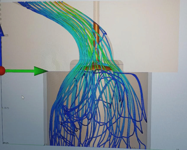
The following images are not from the latest simalutions or designs (to protect my work I hope you'll understand). .
But they are useful for illustrating the post.
As you can see, I carried out a number of CFD simulations in order to optimise the flow of the cylinder head.
This was useful, because it's 'quite complicated' to predict how a fluid will react depending on its velocity and the shape of the duct through which it flows.
The influence of the shape of the intake manifold on the flow is important, and simulations make it easier to interpret the results.
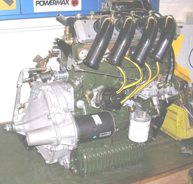
(non-contractual photo)
finally, after a few (many) hours, I managed to get a complete design
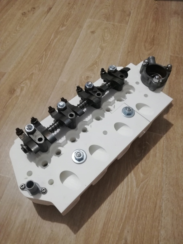
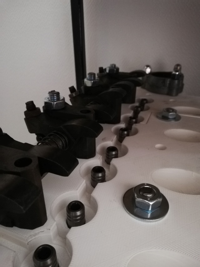
I've printed the whole thing out to check it.
but as it's a big piece, i had to do it in four parts, you can see the joins and the lack of detail, effectively it's a lightened version because concerning the time it's the equivalent of more than 4 days of printing 24/24.
threaded rods are only used to hold 3d printed parts in place .
I won't be posting any photos of the chambers, final ducts or intake manifold for the time being. However, I hope you'll be interested in the project, and I'll be happy to talk about it.
Cheers
I don't know if this is the right place to talk about this project, but feel free to move it if you need to.
For those of you who don't know me, let me introduce myself quickly. I've been working on minis since I was twelve thirteen years old, and I've learnt a lot with these cars (carburetion, ignition, mechanical design, etc.).
Now, as an industrial engineering student, I wanted a project that was a bit more substantial and complete than what I'd been able to do up until now.
As some of you know, I have been working for a while time on the modelling of 8 port cylinder heads.
(as Trog was able to do with his cylinder head, thanks for sharing!)
The obejctive would be to revive the group two cylinder head.
So the first step was to read the documentation for this competition.
(source mk1 forum)
and finally, the regulations only require a few elements to be able to respond to this group's cylinder heads, which is good news!
After a year's research, I was able to start the work of modelling, understanding and analysing, which will enable this model to be competitive.
This work required a lot of time, a number of simulations, and also the development of a number of 3D printed prototypes.
The first of many steps was to determine the location of the important components of the cylinder head, i.e. the studs, the rocker arm passages, the coolant passages and the oil passages.
Once the elements had been designed, I printed them out to check the accuracy of the design.
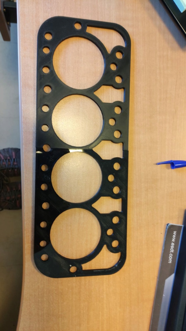
Next step, the shape of the intake and exhaust ducts and the combustion chamber had to be determined.
Although as an engineering student I have access to interesting resources, but this part was extremely time-consuming.
The following images are not from the latest simalutions or designs (to protect my work I hope you'll understand). .
But they are useful for illustrating the post.
As you can see, I carried out a number of CFD simulations in order to optimise the flow of the cylinder head.
This was useful, because it's 'quite complicated' to predict how a fluid will react depending on its velocity and the shape of the duct through which it flows.
The influence of the shape of the intake manifold on the flow is important, and simulations make it easier to interpret the results.
(non-contractual photo)
finally, after a few (many) hours, I managed to get a complete design
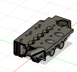
I've printed the whole thing out to check it.
but as it's a big piece, i had to do it in four parts, you can see the joins and the lack of detail, effectively it's a lightened version because concerning the time it's the equivalent of more than 4 days of printing 24/24.
threaded rods are only used to hold 3d printed parts in place .
I won't be posting any photos of the chambers, final ducts or intake manifold for the time being. However, I hope you'll be interested in the project, and I'll be happy to talk about it.
Cheers
-
- 1275 Cooper S
- Posts: 1264
- Joined: Thu Jun 24, 2010 11:55 pm
- Location: Tasmania, Australia
- Has thanked: 3 times
- Been thanked: 7 times
Re: 8 ports cylinder Head project
Very interesting project, keep us updated.
Tim
Tim
1951 Morris Commercial J Type Van
1955 BSA C11G
1961 Morris Mini Traveller
1969 Triumph TR6R
1977 Leyland Moke Californian
1955 BSA C11G
1961 Morris Mini Traveller
1969 Triumph TR6R
1977 Leyland Moke Californian
- timmy201
- 1275 Cooper S
- Posts: 1915
- Joined: Mon Jun 10, 2013 9:57 am
- Location: Australia
- Been thanked: 4 times
Re: 8 ports cylinder Head project
I saw this video from KAD as they’re 3D scanning an 8 port head
https://www.instagram.com/reel/CvdF2wBo ... BiNWFlZA==
You do not have the required permissions to view the files attached to this post.
-
- Site Admin
- Posts: 19843
- Joined: Thu Jun 24, 2010 11:30 am
- Location: Away with the Faries
- Has thanked: 2 times
- Been thanked: 5 times
Re: 8 ports cylinder Head project
Great to see that you have broken cover on this very interesting project. I look forward to continuing to follow your progress.
M
M
-
- 1275 Cooper S
- Posts: 1291
- Joined: Sun Feb 19, 2012 11:11 am
- Location: Somewhere west Switzerland...
- Been thanked: 3 times
Re: 8 ports cylinder Head project
Hej!
This is a very interesting Project you are doing here!
Crazy what doors the new technology open...
Keep us updated!
This is a very interesting Project you are doing here!
Crazy what doors the new technology open...
Keep us updated!
I promise i won't buy another MkI...
-
- 1275 Cooper S
- Posts: 1189
- Joined: Mon Jul 05, 2010 8:40 pm
- Location: Northern Ireland
- Has thanked: 4 times
- Been thanked: 4 times
-
- Basic 850
- Posts: 68
- Joined: Wed May 27, 2015 5:32 pm
- Location: France
Re: 8 ports cylinder Head project
Thank guys
Actually, the software doesn't do everything on its own (at least not yet).
I've lost count of the hours I've spent trying things out, modifying them and trying again. But you're right, it allows us to tinker in a different way .
Actually, the software doesn't do everything on its own (at least not yet).
I've lost count of the hours I've spent trying things out, modifying them and trying again. But you're right, it allows us to tinker in a different way .
- MiNiKiN
- 1275 Cooper S
- Posts: 947
- Joined: Tue Oct 10, 2017 3:15 pm
- Location: Graz/Austria // NN1 4ST previously
- Has thanked: 18 times
- Been thanked: 9 times
Re: 8 ports cylinder Head project
Great project, which very much ticks some boxes of my favourite fields of Mini interests. I'll watch this space....
Yes I am a nerd: I am researching the Austrian Mini-racing scene of the 60s and 70s
-
- Basic 850
- Posts: 68
- Joined: Wed May 27, 2015 5:32 pm
- Location: France
Re: 8 ports cylinder Head project
Good evening everyone,
With the aim of improving our mini engines I had a few questions.
I'm going to do a dynamic CFD analysis of the cylinder head, but before I start I had a few questions.
I'm not going to do it 10 times because the calculation times are quite long.
In order to be as accurate and close to reality as possible, I want to get closer to a " realistic " configuration.
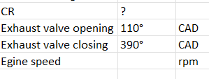
1# I have doubts about the CR to apply, a CR that is not just theoretical (ideal), I was thinking of 10.3 is a good aim ?
2# Similarly for the aac what should I simulate, to keep things simple I have in mind a range of aac Sw10 or Sw23.
However, I don't have the Sw23 timing and I'm not sure about the Sw10 timing.
3# Same for the rotation speed,
the table is with Sw10 timing
If some have already done this kind of simulation, advice is welcome.
-
- 1275 Cooper S
- Posts: 1189
- Joined: Mon Jul 05, 2010 8:40 pm
- Location: Northern Ireland
- Has thanked: 4 times
- Been thanked: 4 times
Re: 8 ports cylinder Head project
I'd go straight away for 649 style camshaft timing and compression of at least 11 to 1
- timmy201
- 1275 Cooper S
- Posts: 1915
- Joined: Mon Jun 10, 2013 9:57 am
- Location: Australia
- Been thanked: 4 times
Re: 8 ports cylinder Head project
I think a problem that people can fall into with 7/8 port heads is not building a complete engine spec to compliment the big port head. If you go too mild on the compression and cam you’ll have the poor combination of weak low end performance due to the larger intake/exhaust ports and reduced top end performance due to the low comp and cam limiting flow and rpm.
Of course if you’re custom designing the head from scratch you can try and get the flow and performance characteristics in the range you’re going to be driving
What’s the end goal for the project? Is it to replicate the head identically to how it was in period? Are you trying to improve it? Is it going to be used on a road/track car?
-
- Site Admin
- Posts: 19843
- Joined: Thu Jun 24, 2010 11:30 am
- Location: Away with the Faries
- Has thanked: 2 times
- Been thanked: 5 times
Re: 8 ports cylinder Head project
I agree with the comments that have already been made. The big advantage of all 8 ports is being able to take advantage of far more radical cams than you can get away with on a 5 port.
Personally, I'd base it around a Sprint type cam running 1:1 or so. Using a very mild cam & low CR doesn't give any benefit with 8 ports.
-
- Basic 850
- Posts: 68
- Joined: Wed May 27, 2015 5:32 pm
- Location: France
Re: 8 ports cylinder Head project
Thank you.
In fact, that's what I wanted to do in the first place.
In my opinion, there's no point in making a simple copy, it will physically look like a weslake, but the aim is to surpass the performance.
I think it will be quite different.
Coming back to the camshaft, the problem is that I don't have the timings.
If anyone has any information (pm if needed), not with the aim of producing camshaft - there are enough on the market - but more to be able to simulate with a recent, high-performance profile.
-
- Site Admin
- Posts: 19843
- Joined: Thu Jun 24, 2010 11:30 am
- Location: Away with the Faries
- Has thanked: 2 times
- Been thanked: 5 times
Re: 8 ports cylinder Head project
Cam data for649, Sprint & Super-Sprint.
You do not have the required permissions to view the files attached to this post.
-
- 850 Super
- Posts: 247
- Joined: Sun Mar 11, 2012 9:50 am
- Location: Denmark
Re: 8 ports cylinder Head project
Talk to Minispares North, they can give you details about the range of cams they sell, and they are "modern designs"
-
- Site Admin
- Posts: 19843
- Joined: Thu Jun 24, 2010 11:30 am
- Location: Away with the Faries
- Has thanked: 2 times
- Been thanked: 5 times
Re: 8 ports cylinder Head project
Most of the Minispares 8 port cams are not modern designs, they are old faithfulls.
-
- 1275 Cooper S
- Posts: 1254
- Joined: Thu Jun 24, 2010 11:26 pm
- Location: East Cumbria
Re: 8 ports cylinder Head project
Kent cams will give you all the timings. I have them as pdf's
PART No C-AEG310 Race
INLET EXHAUST
CAM LIFT 8.62mm 8.62mm
VALVE LIFT (Theoretical ratio1.28:1) 10.67mm 10.67mm
DURATION @ 0.4mm 310 300
TIMING FIGURES @ 0.4mm 49/81 76/44
FULL LIFT 106 ATDC
VALVE CLEARANCE 0.4mm 0.4mm
PART No C-AEG311 Rally
INLET EXHAUST
CAM LIFT 8.19mm 8.62mm
VALVE LIFT (Theoretical ratio1.28:1) 10.07mm 10.67mm
DURATION @ 0.4mm 306 300
TIMING FIGURES @ 0.4mm 53/73 74/46
FULL LIFT 100 ATDC
VALVE CLEARANCE 0.4mm 0.4mm
PART No C-AEG312 Road
INLET EXHAUST
CAM LIFT 7.99mm 7.99mm
VALVE LIFT (Theoretical ratio1.28:1) 9.82mm 9.82mm
DURATION @ 0.4mm 274 274
TIMING FIGURES @ 0.4mm 27/67 67/27
FULL LIFT 110 ATDC
VALVE CLEARANCE 0.4mm 0.4mm
Wanna see what I'm playing with? Youtube Channel
Caution may contain 8 Ports, Xe's and VTec's, I don't do standard!
-
- Basic 850
- Posts: 68
- Joined: Wed May 27, 2015 5:32 pm
- Location: France
Re: 8 ports cylinder Head project
ok thanks
if I go to the end it will certainly be interesting to test the whole thing with a camshaft that respects App K specification.
But, I guess the difference of some degree will not affect the design
if I go to the end it will certainly be interesting to test the whole thing with a camshaft that respects App K specification.
But, I guess the difference of some degree will not affect the design
-
- 998 Cooper
- Posts: 655
- Joined: Tue Mar 31, 2020 8:44 pm
- Location: The Netherlands
- Been thanked: 3 times
Re: 8 ports cylinder Head project
This is a very interesting project I look forward to following. It seems you're making quite some headway (if you'll pardon the pun). Although some time yet; how will you have the head made in the end, will you print it and then use a lost wax casting method?
Of course I know what a dipstick is, you get called something often enough you look it up!
- MiNiKiN
- 1275 Cooper S
- Posts: 947
- Joined: Tue Oct 10, 2017 3:15 pm
- Location: Graz/Austria // NN1 4ST previously
- Has thanked: 18 times
- Been thanked: 9 times
Re: 8 ports cylinder Head project
I did PM you with a recommendation for a company who do prototype casting from 3D-printed cast models, baptiste. Don't know if you have seen it.
Yes I am a nerd: I am researching the Austrian Mini-racing scene of the 60s and 70s